Last Tuesday (30/07/19), during the maintenance, we set up a power monitor and started the works to set a frequency monitor of the Master Laser. These monitors will help us to better understand its behavior and give us information on whether or not it is responsible for the fast unlocks.
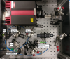
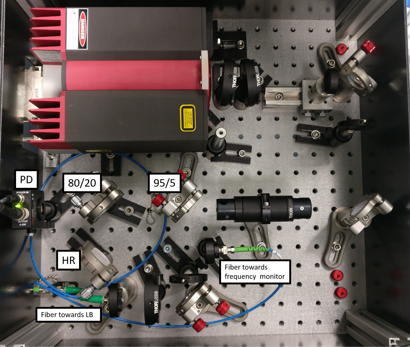
To do so, we changed the penultimate folded mirror used to inject into the fiber going on the laser bench by a Beam Splitter 95/5 (see picture 1).
We were working at low power. Before changing the mirror we had 37.2 mW at the output of the fiber. After having set up the beam splitter and realigned into the fiber we had 35.8 mW at the output which correspond to a loss of 3.8 %. The difference with the expected 5 % must come from a better alignment into the fiber.
From that point we worked with the transmission of the BS to set up the monitors.
We placed a photodiode (PDA36A-EC from Thorlabs) in transmission of another beam splitter transmitting about 20 % of the power (see picture 1).
We measured its offset: -25.7 mV and did a calibration at low power: 0.289 mV for a measured power of 35.8 mW (before the Faraday Isolator).
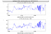
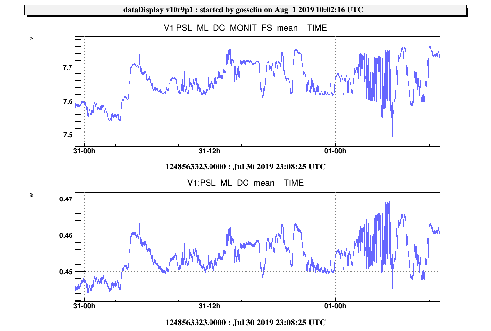
The signal of this photodiode is acquired at high frequency (500 kHz) under the name: PSL_ML_DC_MONIT_FS (picture 3).
Then we placed a HR mirror which, together with the last beam splitter, allows us to inject into a fiber that will later be plugged to the frequency monitor presented in VIR-0778A-19.
Unfortunately the collimator that we had was too different from the one used to send the power towards the laser bench and the matching was too bad to get a good coupling.
We are buying the same collimator. During the next intervention, we will set it up and we should get a better coupling.
We did not make any direct measurement of the available power. However we can estimate it. There is 80% x 5% = 4% of the ML power available. This power is about 680 mW (entry 44712), so about 27 mW are available. Even a coupling of about 40 % should allow us to get the needed 10 mW for the frequency monitor.
When finished those works, we replaced the ML box in the rack.
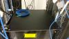
To be noted that the cable of the photodiode avoid us to close the box properly. We will have to cut a part of the cover. (see picture 2).
We increased the ML pumping current to its nominal value (1.773 A). The monitor of the ML power placed on the LB give us a loss of 10 % (from 500 mW to 450 mW) while we were expecting only 5%. It does not affect the SL loop but we will investigate those extra losses next time.