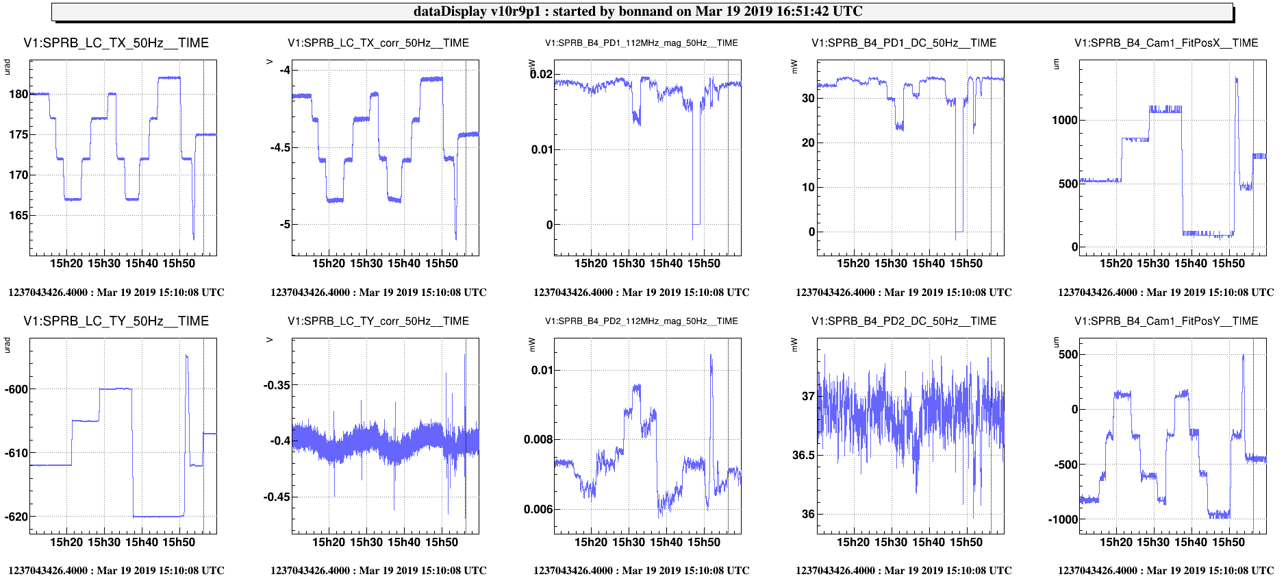
After the daily meeting, I try to align SPRB and the B4 photodiodes.
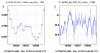
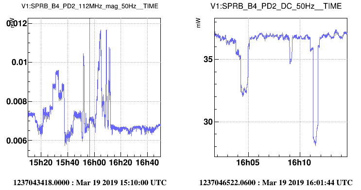
First, I put the bench in TX and TY at different positions to see the effect on the DC power of B4_PD1 and B4_PD2 and on the sidebands (i.e. SPRB_B4_112MHz_mag channel coming from B4_PD2), see figure 1.
- One can see that the maximum power on the DC does not give the maximum on B4_112MHz_mag, on the contrary the B4_112MHz_mag signal gets higher when we start clipping the beam (B4_PD2_DC going lower).
Then, I finally change the setpoints of the bench, to get the maximum power on B4_PD1 :
- SPRB_LC_TX from 180 urad to 175 urad.
- SPRB_LC_TY from -612 urad to -605 urad.
At this setpoints, the beam in B4_PD2 is a bit misaligned so I used the picomotors in front of it to maximize the DC, I did at the end :
- SPRB_Mmot4_V ==> -4000 steps.
- SPRB_Mmot4_H ==> 6500 steps.
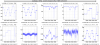
Figure 2 shows the B4_PD2_112MHz_mag and B4_PD2_DC while moving the picomotors, same observation as before maximum of DC and 112MHz_mag are not at the same position.
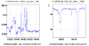
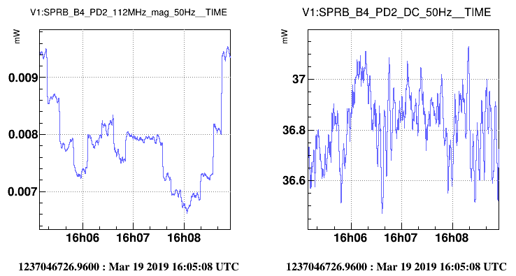
Figure 3 shows a zoom of figure 2, there might be a way to get a higher B4_PD2_112MHz_mag without loosing power on B4_PD2_DC...
It would be interesting to look at the phase camera data to understand this strange behaviour.
I also attached the log file of the action done on SPRB setpoints and SPRB_B4_Mmot4 picomotors.