To measure the sensing and driving matrix of BPL, a sinusoidal signal at 2 Hz, with 0.2 V amplitude was injected on channels:
- PZT_EIB_M1BH_CORR
- PZT_EIB_M1BV_CORR
- PZT_LB_M14H_CORR
- PZT_LB_M14V_CORR
Directly on the piezo correction signal. The BPL loop was open while injecting noise.
The signals were injected respectively at GPS times [1464363022, 1464363121, 1464363296, 1464363397] , each injection lasted for 60 s.
The channels QF_h_norm, QF_v_norm, QN_h_norm and QN_v_norm were monitored to see the effect of each piezo on each quadrant.
Piernicola's matlab script "Sensing_matrix_BPL.m" was used to compute the matrices:
sensing_matrix =
-0.6230 -0.0278 0.0033 0.0012
0.0233 -0.3838 0.0010 -0.0059
-0.5035 0.0063 0.4332 0.0151
0.0154 0.3421 0.0166 0.2886
driving_matrix =
-1.6099 -0.1078 -1.8808 0.3216
0.1242 -2.6459 0.0738 3.1261
0.0118 0.0090 2.3271 -0.1449
0.0085 -0.0545 -0.1126 3.5359
However, the loop does not close. We tried to adjust the setpoint of the piezo (TILT/SHIFT_X/Y_CORR_SET) so as the norm signal of the QPDs come close to 0, and tried several values of the DRIFT_FILTER gain but we did not succeed.
Paolo got a similar driving matrix, the values of the set point has to be studied more deeply.
2 comments
The sensing and driving matrices measured in the precedent post 69150 were wrong, due to an error on the threshold on the phase that separates the positive from the negative responses between the piezo and the quadrants. The new matrices were computed:
sensing_matrix =
-0.6230 -0.0278 0.0033 0.0012
0.0233 -0.3838 -0.0010 -0.0059
-0.5035 -0.0063 -0.4332 -0.0151
0.0154 0.3421 0.0166 -0.2886
driving_matrix =
-1.5909 -0.1001 1.8540 -0.0972
0.1081 -2.5520 0.0166 -3.0190
-0.0128 0.0071 -2.2893 -0.1237
-0.0080 0.0517 0.1270 -3.3971
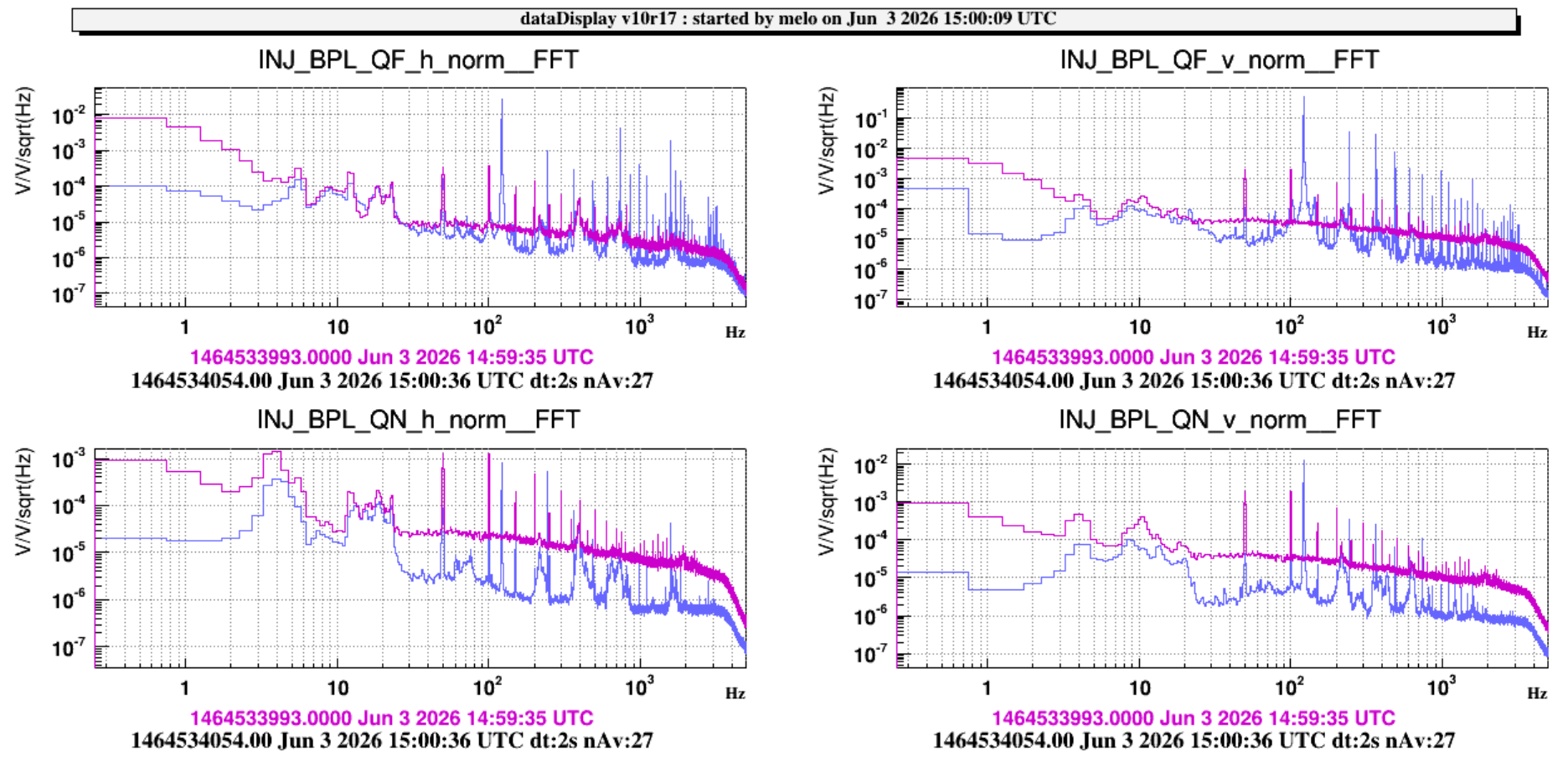
Using the new driving matrix, we managed to lock the BPL loop in drift control (f < 5 Hz). And then in broadband.
When the BPL is locked in broadband, a 122 Hz signal appeard on the QPD signal spectrums.
In order to measure the open loop transfer function, the BPL loop was open and a colored noise signal with a 0.001 V amplitude was injected on the channels:
To see the transfer function at low frequency, a 0.03 V signal at frequency < 20 Hz was injected on the same channels at the times:
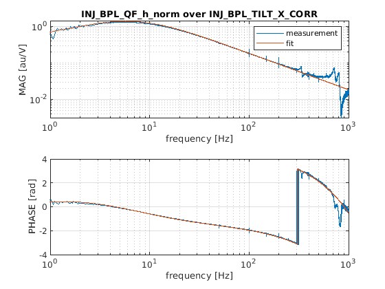
The shape of the open loop transfer functions from the CORR signal to the corresponding of the quadrant signals are similar. The following plot is a transfer function from TILT_X_CORR signal to QF_h_norm during a low frequency injection:
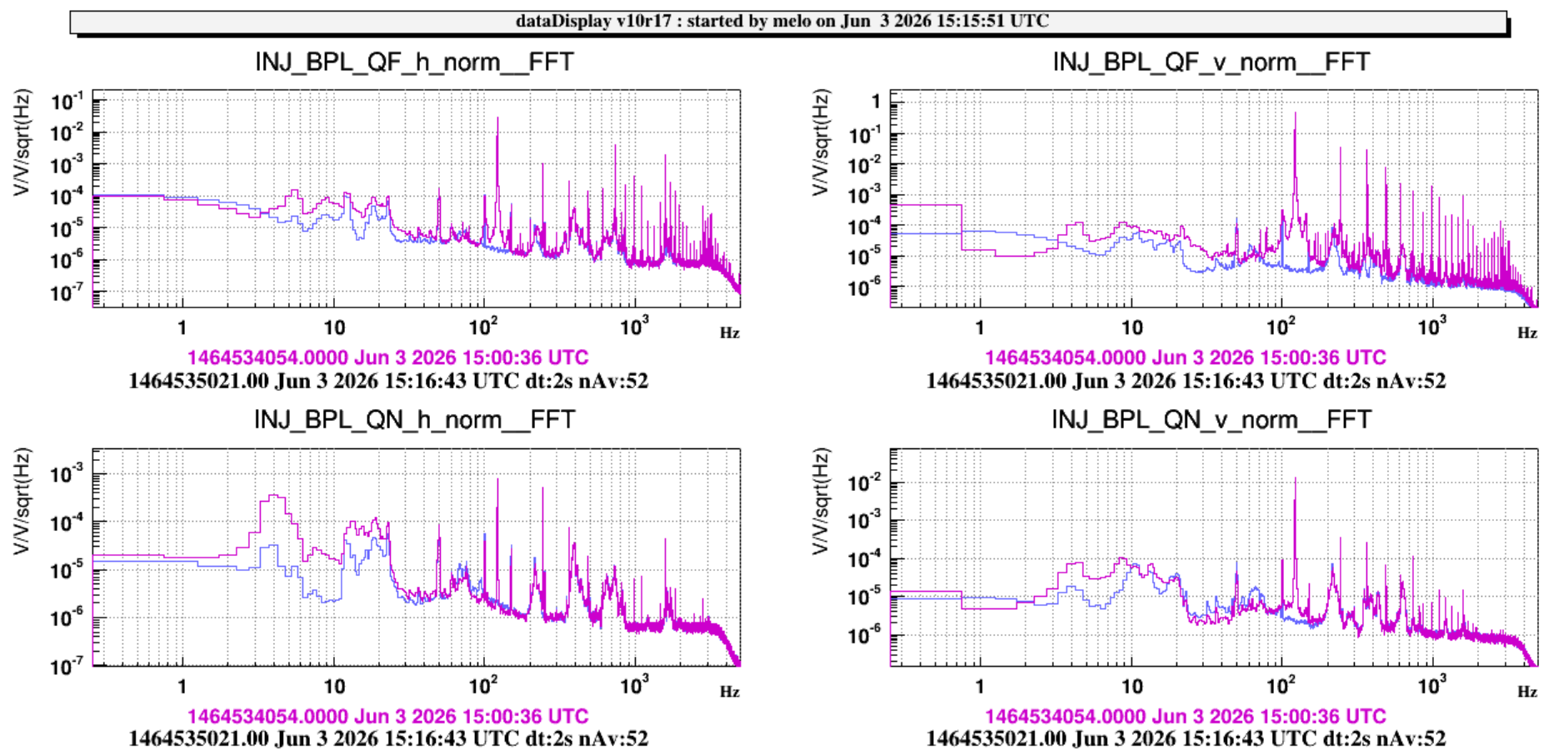
The 122 Hz noise was due to a saturation of the control loop, so the loop filter was changed. The QPDs signal spectrums in closed loop, with the old and with the new filter are shown in the following plot:
The 122 Hz signal disapeared.
The "tranfer function" measured in the previous logbook entry is the tranfer function from a noise injected before the driving matrix and after the filter, to the normalized signal of the quadrants. So when we inject a noise on one of the TILT/SHIFT signal, this noise is only visible on the corresponding quadrant signal. In the example given in the logbook entry, the noise is injected on TILT_X signal, and arrives on the far-field quadrant horizontally. The next image is a scheme of the BPL loop with the injected signal :

Another remark: EIB was not suspeded when preforming all the measurements. So they have to be repeated with the EIB suspended, which may affect the measured sensing matrix, and so the corresponding driving matrix.