Tonight we started the shift after the work performed to try the OMC lock.
The plan was to measure: 1 - arms losses, 2 - Gouy phase and 3 - Finesse
In order to keep the beam always centered on the B1p PDs, even when the North arm was misaligned, we opened the SDB1 B5 drift control and changed the offset in the following way:
LC_TX_set: from -155 to -100
LC_TY_set: from -950 to -870
After the measurements, the drift control has been closed, while we left the new offsets for the SDB1_LC.
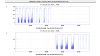
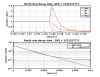
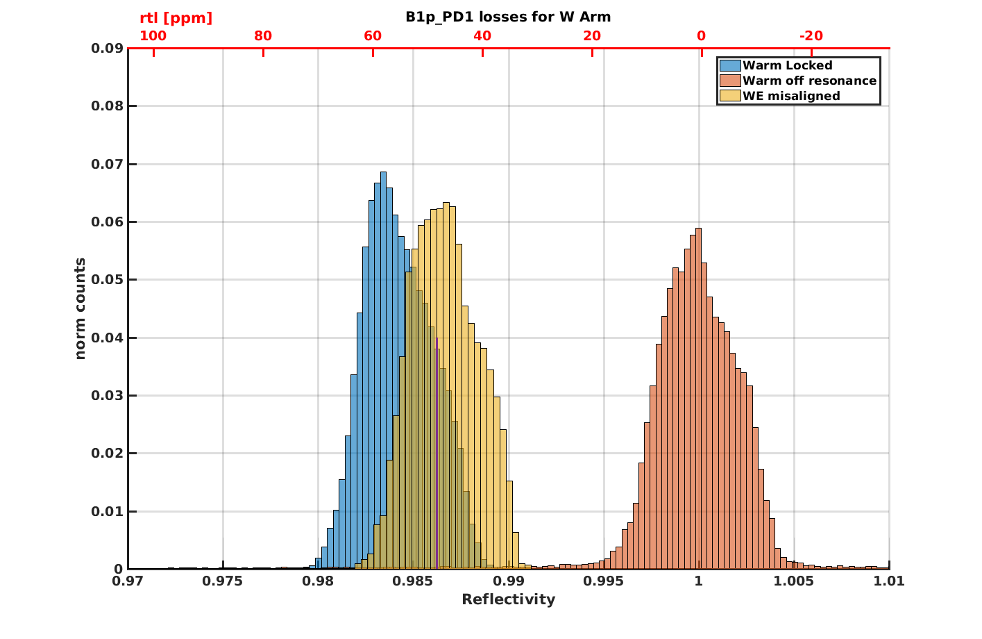
1 - ARMS LOCK-UNLOCK
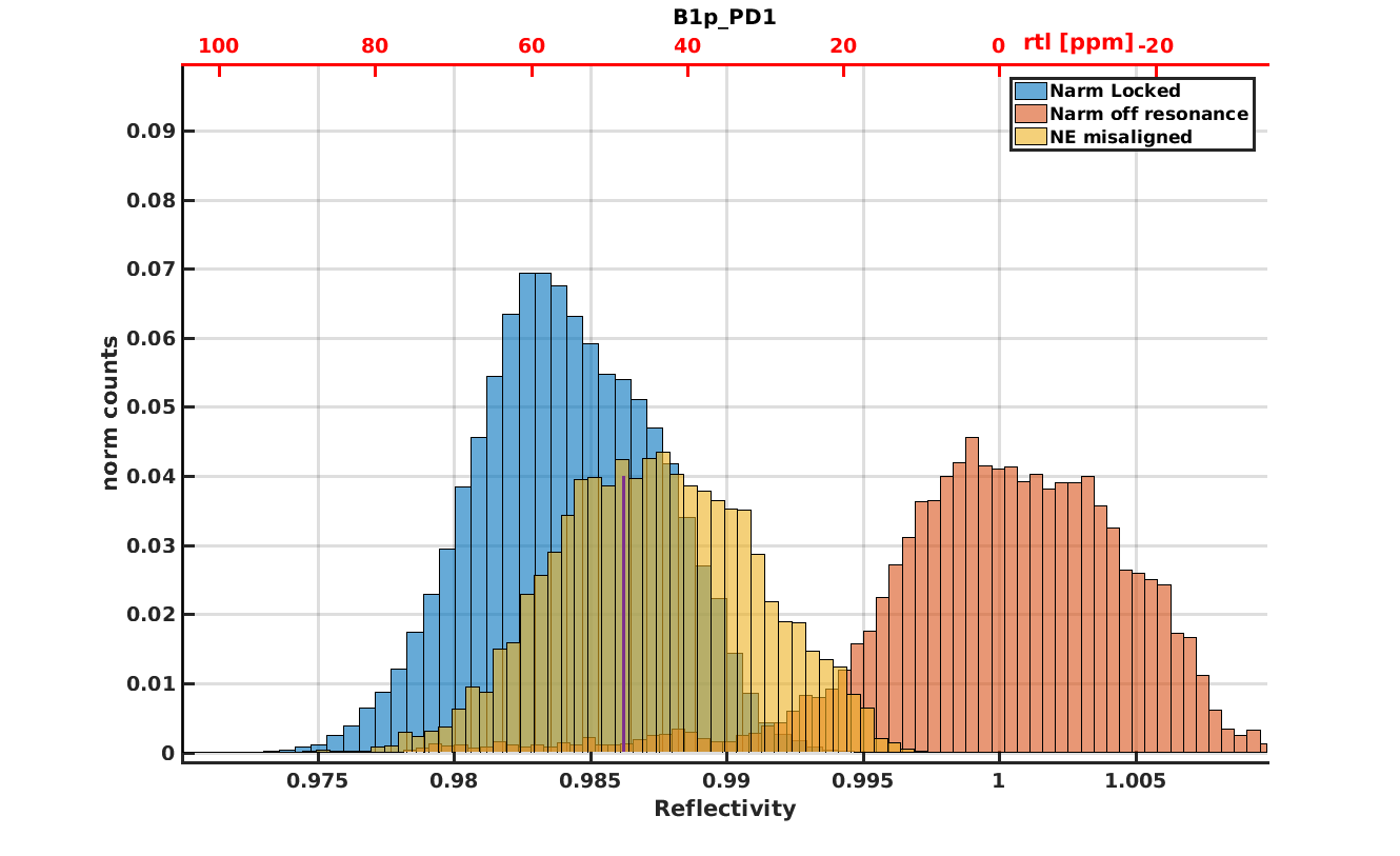
In the few hours left, we performed some lock-unlock measurements in order to measure the losses. As reported in #41555, we performed the measurements of the ITM reflectivity in three different conditions:
- cavity locked
- cavity unlocked (but still aligned)
- cavity unlocked and ETM misaligned (only ITM aligned)
GPS start West = 1221505594
GPS start North = 1221509643
(see figure 1)
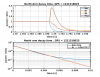
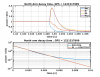
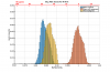
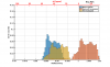
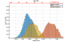
2 - FREE SWINGING
North (6MHz with modulation depth at 5 dBm to allow the RFC to stay locked, 8MHz and 56MHz at -10 dBm)
GPS = 1221514610, 1221514818, 1221515051
8MHz modulation depth increased to -5 dBm to have one more reference in the FSR
GPS = 1221515254
West (same conditions as for the North)
GPS = 1221516268 and following
8MHz modulation depth increased to -5 dBm
GPS = 1221516863
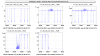
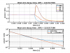
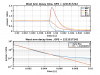
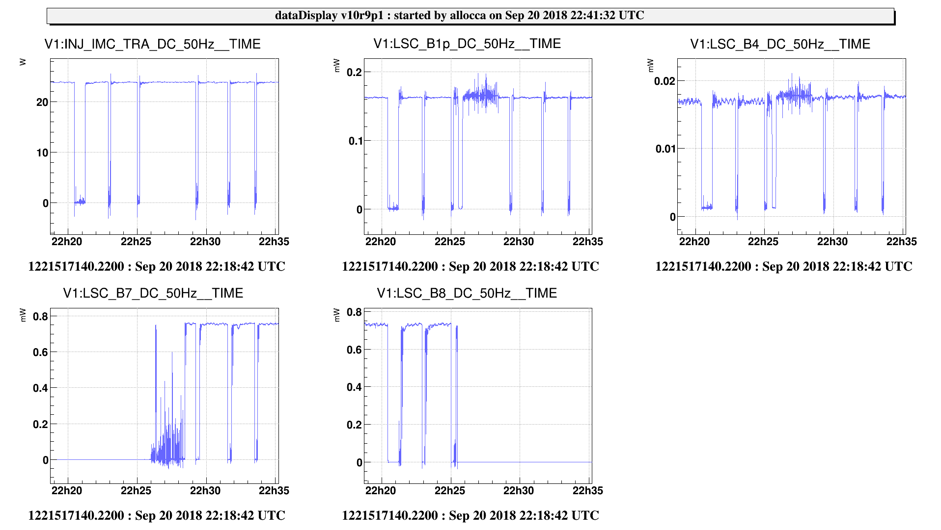
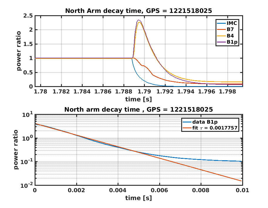
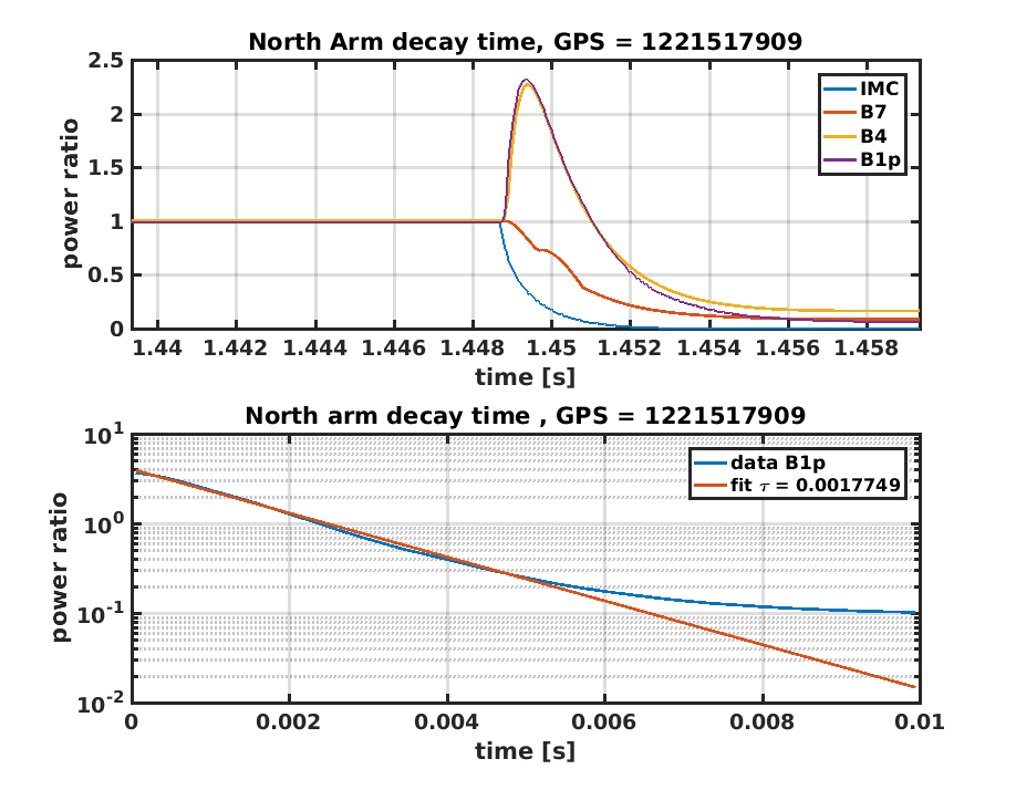
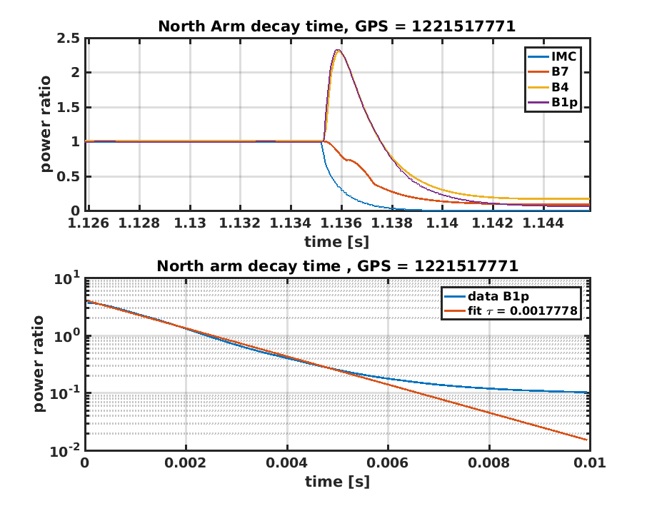
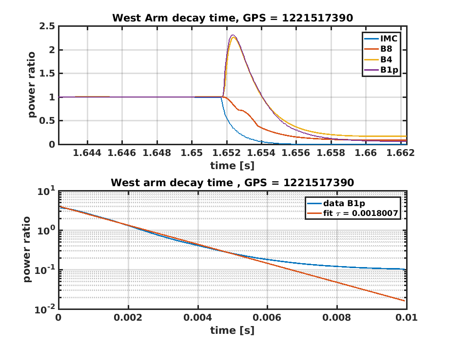
3 - IMC FAST UNLOCK
We locked one arm at the time and unlocked the IMC in order to cut the input light.
The GPS can be extracted from figure 2.
The analysis of the data will follow.
We tried to engage the lock on LN1, but wehad 3/3 unlocks due to the usual SSFS ramp problem, therefore we leave the ITF in recombined.