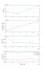
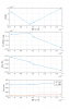
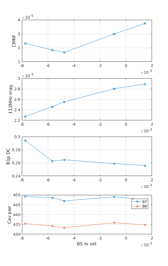
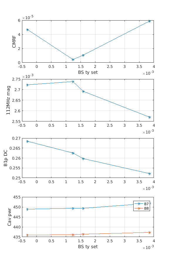
A good part of this morning shift was focused on finding a good working point for the alignment loops on LN3, including BS which is a bit more tricky. We have tuned the Diff+ and the PR by minimizing the power on B1p and maximizing the power on the sidebands senn by B4. INstead, for finding the good working point for the BS we have used as a figure of merit the CMRF. The scope was to find the offset that minimizes the CMRF, the region explored is shown in FIgures 1 and 2 (for TX and TY), together with different relevant probes.
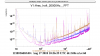
It can be seen that for the TY degree of freedom the minimum of MCRF agrees with good values of sideband gain and a "dark" dark fringe. However, it is not the case for the TX. It seems that a good alignment in terms of sidebands/dark fringe i not compatible with a low CMRF. For the moment we have chosen a good CMRF, since the impact on the sensitivity is quite evident. Figure 3 shows the sentivity curve at the beginning of the BS loop tuning (yellow) and at the end (blue). The high frequency improves significantly, due to the improvement of the CMRF.
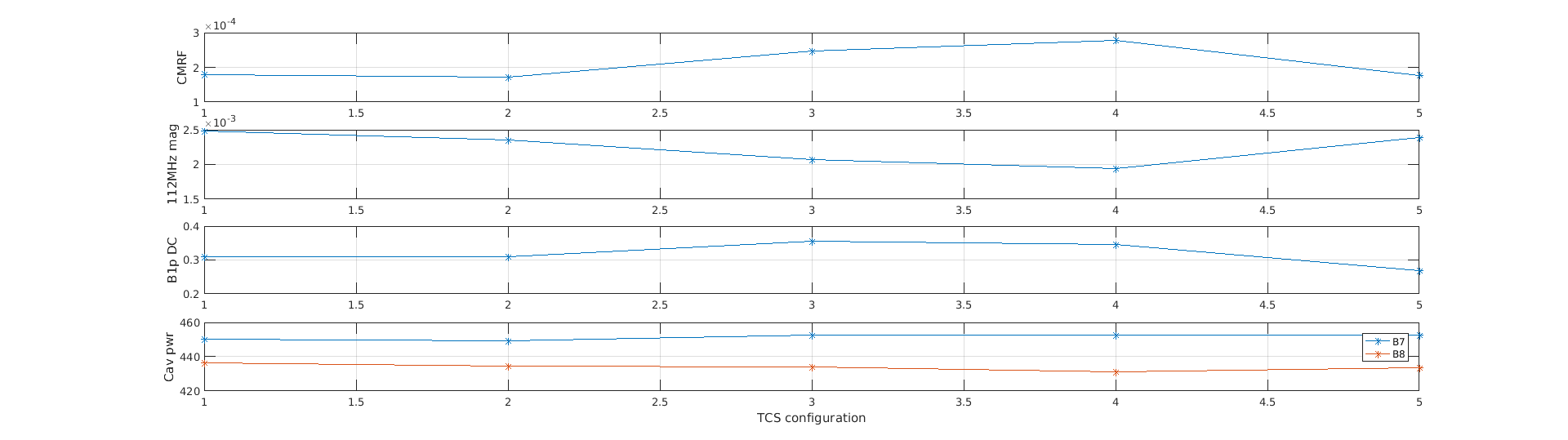
However, the fact that a low CMRF does not agree with a high value of the sidebands for vertical offsets of the BS suggests that we are missing something. One hypothesis was that we are trying to compensate with the BS an asymmetry between the arms so we are misaligning (bad behaviou rof the sidebands) to improve the symmetry of the cavities (good CMRF). One parameter to explore is the TCS impact on the CMRF. In order to check it we have plotted the CMRF for different TCS configurations.
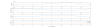
We have used the data of tuesday, since the working point of the alignment was not changed during the whole shift. The steps indicated no the x-axis corresponds to the configurations of the TCS shown in the entry 42442. The point 0 is the one at the beginning of the shift. Figure 4 shows the CMRF, the sidebands power, the power on B1p and the cavity power for each TCS configuration. It can be seen that in this case the CMRF changes for each configuration, but at each point good CMRF is consistent with good recycling gain and good dark fringe. It can be seen that for different TCS configuration the CMRF changes up to a factor 2.
We could try to explore the dependency of the CMRF with respect to the BS and the TCS, trying to make these paraemters to converge.