* OMC bridge changed to allow birefrigence tuning with additional side screws
* obtained 0.75e-3 polarization mismatch without using the side screws
* obtained 98% OMC2 throughput with a coarse alignment and mode matching between the two OMCs
* the OMC1/OMC2 resonant mode seems to have 7e-3 of P-polarization
* the OMC PZTs are now tightened at the nominal 20cNm instead of a few cNm
=> should allow faster lock acquisition but increases coupling of PZT driving electronic noise (it was a factor 30 below h(t) despite a large offset on the OMC1 locking point)
* results may change after going into vacuum and fine alignment
To tune more finely the birefrigence of the OMCs we have prepared new
bridges above the OMC. Instead of having one hole for tightening the
PZT mounted on top of the OMC with a screw. The new bridges have three
holes. One for the PZT screw, and two holes for screws compensating
the briefrigence caused by the PZT screw.
To land SDB1 on the safety bolts we have lifted the nuts on the bolts
all the way to the top of the blot to prevent the bolts from falling
into the safety catch holes that are not exactly well aligned with the
controlled position of the bench (by ~0.5mm). We then lift the bolts
till they lightly touched the bench, and then we put weights on top of
the bench, and screwed additional weights underneath the bench to
block it. We then used BS to fine align the direct NI reflection beam
on OMC1.
To change the bridges we have removed the OMCs from the support block
and left them on SDB1. We unscrewed the whole OMC support block and
took it to the clean room. We put chocks (clamps) to mark the position
of the support bock before removing it. To remove the bridge we need
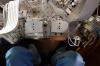
to remove the copper plate below. At that point we noticed that unlike
the spare setup at LAPP the PZT wires are going through the screw hole
in the middle of the copper plate which we wanted to use for the
bridge instead of a dedicated small cable hole (see figure 1).
We thank Vincenzo for lending us a soldering iron and flux free solder to
unsolder the OMC PZTs, change holes used for the PZT wires and
resolder the PZT. We also changed the kapton insulation around the
PZTs. After that we could mount the new bridges. To be sure to have a
good thermal contact we have changed the indium sheets on both sides
of the Peltier cells and underneath the OMCs. On one of the Peltier
cells on one side the indium sheet was stuck (the Peltier cell was
stuck to the copper plate by the indium sheet), so we left it.
We then checked if the new black coated OMC covers fit the copper
support. They did not. We measured them to be 0.2mm more narrow than
the old OMC covers, so they did not fit onto the copper support
plate. We gave them to the LAPP mechanical team that was on site to
file the bottom 4mm of the covers by 0.2mm of material on the inner
side around the bottom of the OMC covers.
Then we installed back the OMC support block on SDB1. While removing
the temporary chocks (clamps) we lost a ~10mm long M6 screw and a
washer inside the bench. It fell through a ~2cm diameter hole that was
designed ~20 years go to pass a beam underneath SDB1 with a
periscope. Note that is no longer possible, as the bottom plate of the
bench has been changed and the corresponding holes have been
forgotten. This free screw should not be a problem for balancing the
bench. During the suspended bench alignement recovery the bench has
been shaken by local controls many times and the balancing did not
change.
Afterwards we put the OMCs on the support, tightened the PZT screw
with a torque of 20cNm and put one screw barely touching the OMC in
the side hole of each OMC bridge in preparation for birefrigence
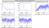
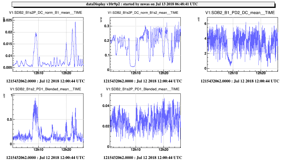
tuning. We then aligned the OMC1 and locked it using the B1s1
photodiode. Figure 2 shows the power on B1s2 and B1s2P, there is also
a ratio of the two photodiode, that shows 0.02. Given that B1s2 sees
only 8% of the power, this correspond to 1.6e-3 of P-polarization in
transmission of OMC1. This was surprisingly good, we spend some time
wondering if we are looking at ghost beam on B1s2P, but we didn't find
any brighter beams.
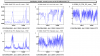
Afterwards we reduced the power on SDB1, by dumping 90% of the power on
the squeezing bench using the Faraday isolator (we installed a beam
dump on the squeezing bench on Monday morning and left it there), and
locked OMC2. Figure 3 shows the PD powers, in particular the ratio of
power between B1s2P and B1_PD2 was 0.006, given that PD2 sees only
half of the power this corresponds to 3e-3 of light rejected by OMC2
in P-polarization.
At that time we have also seen that the error signal on OMC2 was 3
orders of magnitude smaller than for OMC1 for the same PZT
modulation. We went inside the tower and put the modulation frequency
at ~2.5kHz. We could hear clearly the PZT on OMC1 but not on OMC2. We
removed the OMC2 PZT screw and pressed on the PZT with a metal
tweezers handle. At the second attempt we could hear the OMC2 PZT
modulation. Which pointed to a bad mechanical contact and not a bad
soldering. We put back the OMC2 PZT, removed the 5mm longer side screw
and used it to tighten the PZT. The new bridges might be a hundred of
microns taller than the old ones.
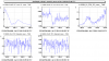
After this we continued with the birefrigence tuning. First locking
only OMC1. We tightened the side screw by 5cNm. This degraded the
birefrigence by a factor 40, B1s2P/B1s2 ratio went from 0.02 to 0.8,
so 6% of P-polarization. This reassured us that we were actually
having a very good birefrigence tuning. We removed completely the side
screw of OMC1. The result is shown on figure 4, the B1s2P/B1s2 dropped
to 0.09, so 7e-3 of P-polarization.
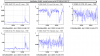
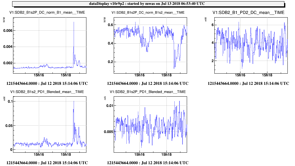
As we were running out of time, we moved on and locked OMC2. Figure 5
shows the result, the B1s2P/B1p_PD2 ratio is 1.5e-3, which means
0.75e-3 of P-polarization rejected by OMC2. Very satisfactory, the
removal of the barely touching screws might be the explanation of the
improvement. Also on figure 5, there is 0.015mW on B1s2_PD1 and
0.007mW on B1s2P_PD2, this corresponds to 0.015*12 + 0.007 = 0.187mW
of power rejected by OMC2, while there is ~5mW on B1_PD2, so 10mW
passing through OMC2 and a throughput slightly above 98%. This is
confirmed by comparing B1s2 on figure 4 and 5 (which are separeted by
a few minutes), the power drops from 0.6mW to 0.015mW, so only ~2.5%
of the power remaining in reflection of OMC2.
In conclusion the resonant mode of OMC1 and OMC2 seems well
polarization matched, with a difference of 0.75e-3. In the past we
have seen that quantity to degrade by a factor 2-3 when fine aligning the
two OMCs. Lets hope that after going to vacuum and fine alignment it
will not degrade by more than a factor few. This common mode has 7e-3
of P-polarization, which will probably result in a ~1% loss at the
OMC1 input. In addition there is 2% of s-polarized light loss between
the two OMCs, some of it could be due to coarse alignment and mode
matching, some to RF sidebands.
There is a motorized lambda plate to tune the polarization impinging
on OMC1 and remove this 1% loss, but it is not connected. After O3
additional cabling for the Faraday and this plate is foreseen. Before
O3 it should be possible to tune it by opening the detection tower and
temporarily disconnecting one of the picomotors.
Note that for all of this work the light resonating in the OMCs is
fluctuating by a factor 3 due to beam alignment fluctuation caused by
the nitrogen flow and the clean air flow in the tower. So it was
impossible to do a good alignment tuning, and everything needs to be
confirmed in vacuum with a good alignment.
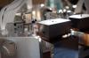
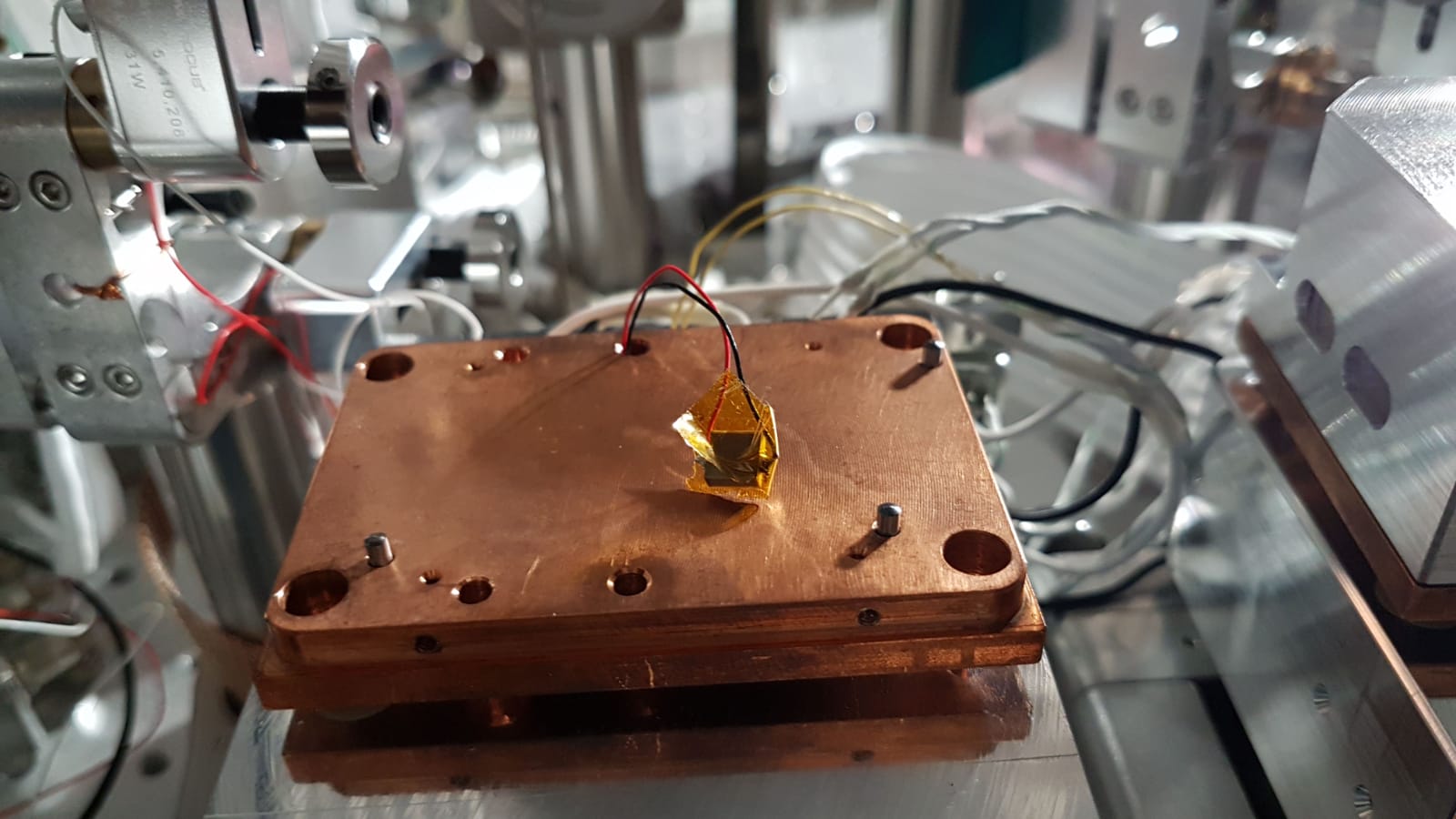
After this tuning, we put the OMC covers that have been filed in the
meantime and checked that it didn't change the polarization
tuning. For OMC2, the cover wouldn't fully go in, the
new bridge seems slightly to tall by ~0.5mm. This would also explain why the PZT
screw became too short. We expect the cover is just sitting on top of
the bridge, and it is in contact in a few points at the bottom around
the copper plate. We left Irene a spare uncoated OMC cover, so its
mechanical resonances can be measured in case we see new bumps in the
h(t) spectrum.
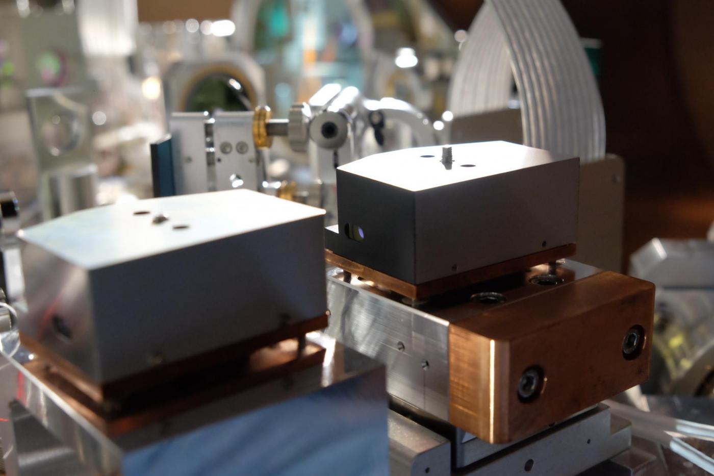
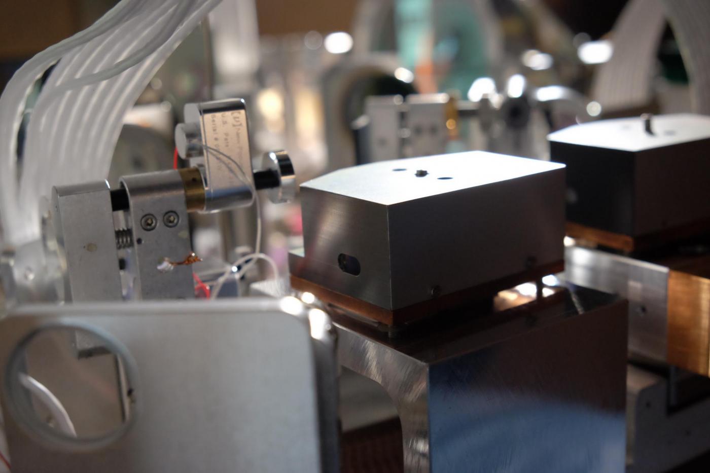
Figure 6, 7 and 8 show the OMCs at the end of the work.

