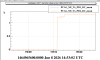
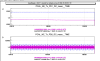
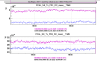
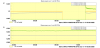
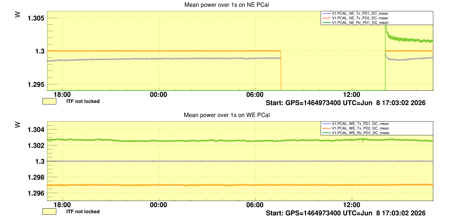
This morning we went at NE to install the new steering mirror and the Rx sphere. The NE PCal is finally on again since 14H UTC. See the last figure with the VIM plot showing the relative calibration of the three power sensors of the NE Pcal.
Note that the responsivity (gain) of the Rx sphere has not been changed, and the gains of the Tx photodiodes neither. They are kept to be the same as during O4. If the NE PCal mis-calibration by 0.9% during O4 was due to optical losses in the M4 mirror, we were expecting that the power seen by Rx would increase by 0.9% compared to the other two photodiodes.
As a first remark, it seems that the relative calibration of Rx sphere and Tx_PD2 is similar than during O5, at better than 0.1%, while the relative calibration of Tx_PD1 has changed by ~0.5%. However, it is difficult to disantangle which sensor calibration has varied. A full recalibration based on WSV or a comparison with the NCal will be necessary to get useful information.
**********************************
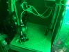
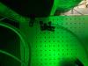
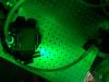
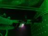
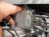
Pictures 1 to 5 show the NE PCal Rx bench with:
- the new mirror (Thorlabs BB1-E03), put with aoi of about 20-25°. The reflectivity of this mirror has been characterized vs aoi at LAPP, as shown in the pre-last figure.
- the Rx sphere, moved to another position than before (since the aoi was 18-19° during O4)
- the temperature and humidity sensor moved behind the sphere.
- the sphere cap and a beam dump to be used during interventions on the bench, also put behind/on the side of the sphere.
Before enabling the power supply (Hameg29) to switch on the sphere, I have switch it off to recover the Ethernet monitoring. Unfortunately, after switch on, the channel 1 was dead (-12 V for the NE_Tx_PD photodiodes), no more providing any voltage. Note that this power supply for NE PCal has already been changed already twice because of similar issue, but on channel 3 instead.
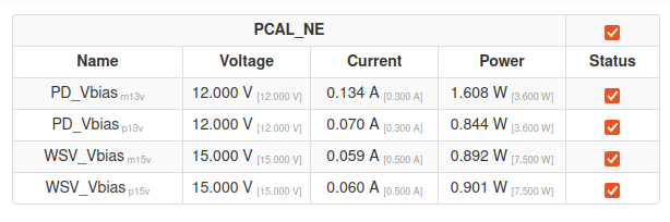
In the afternoon, we have replaced the power supply Hameg29 by the Hameg32. Following an advice from Nicolas Letendre, we have added a cable to connect the grounds of the two pairs of channels: 1 and 2 (providing the -12 V and +12 V for the photodiodes) and 3 and 4 (providing the -15 V and +15 V for the sphere).
Another change, the maximum current setup is now the same as at WE : 0.3 A for channels 1 and 2, and 0.5 A for channels 3 and 4 (while until today it was 0.3 A for the four channels).
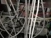
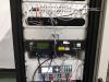
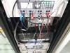
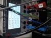
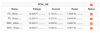
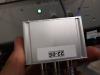
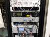
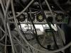
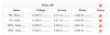
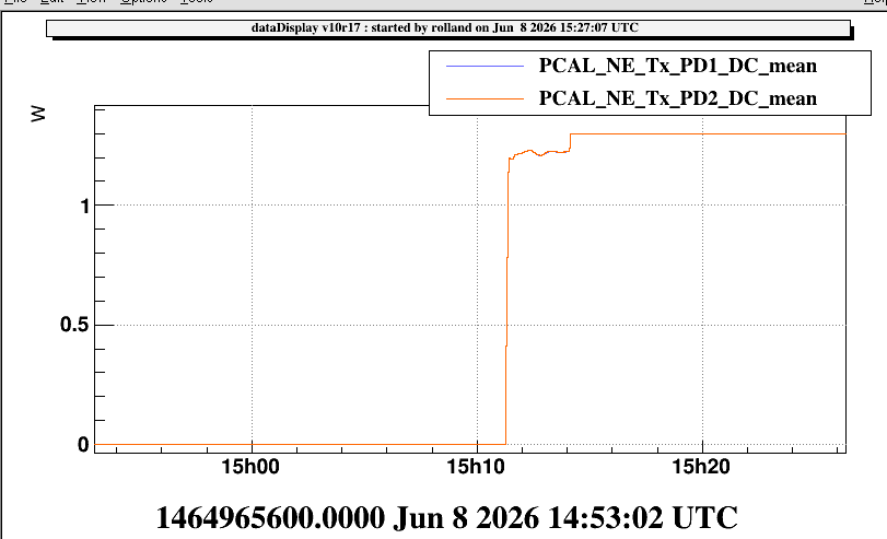
Figures 7 to 10 show the NE PCal electronics in the rack, with some vision of the cabling, and the power supply panel information when the laser is off and when the laser is set to 1.3 W. Figure 11 shows the id of the follower-circuit used for the NE Rx sphere (before the ADC).
Figure 6 shows the rear panel of the laser driver: I noticed that the leftmost fan is not working (and another fan seems to be a bit noisy).
**********************************
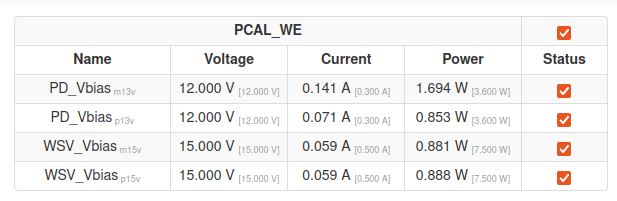
Figures 12, 13, 14 and 15 are pictures of the WE Pcal rack, id of the WE Rx follower circuit, rear panel of the laser driver, with all fans working, and power supply panel with the laser set at 1.3 W.
**********************************
Figures 10 and 15 show the information about the setup of the NE and WE PCal Hameg power supplies, as well as the current values delivered when the laser is set to 1.3 W.
