This morning, we performed other interventions regarding the problem about the heating up of the neovan head seen these last weeks.
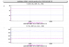
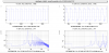
The first thing has been to send the flow of the chiller only in the neovan head to try to flush out the potential dirt slowing the flow down. Indeed there were some (picture 1).
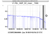
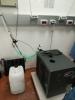
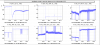
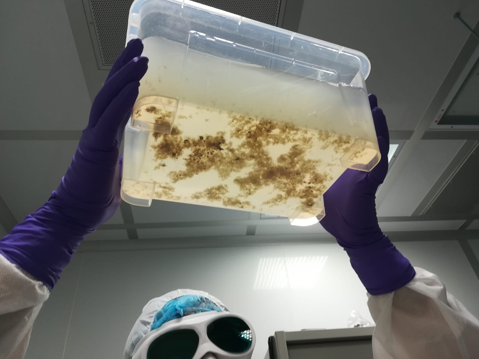
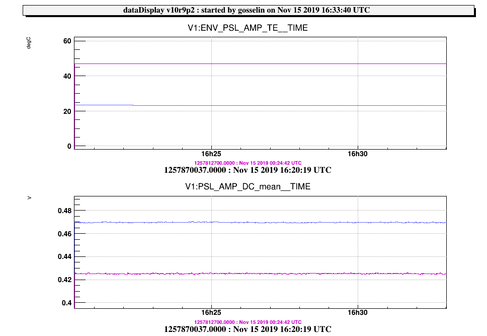
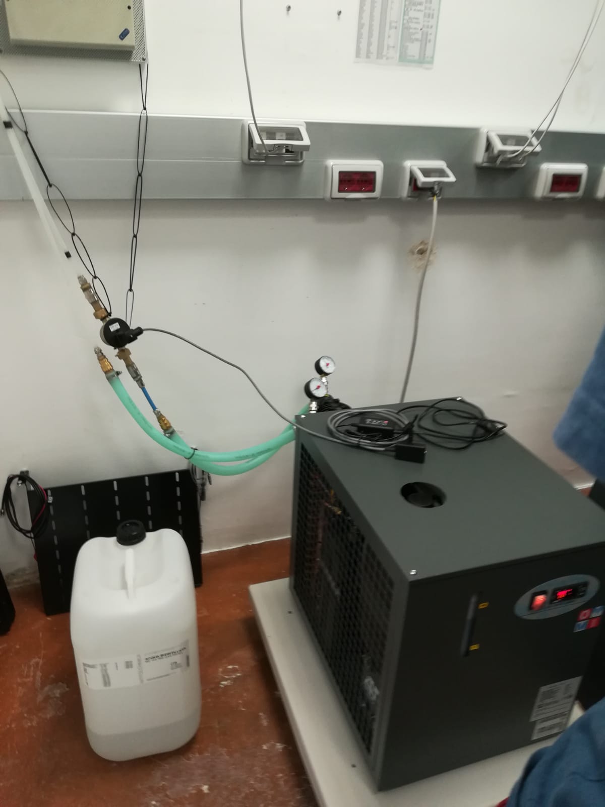
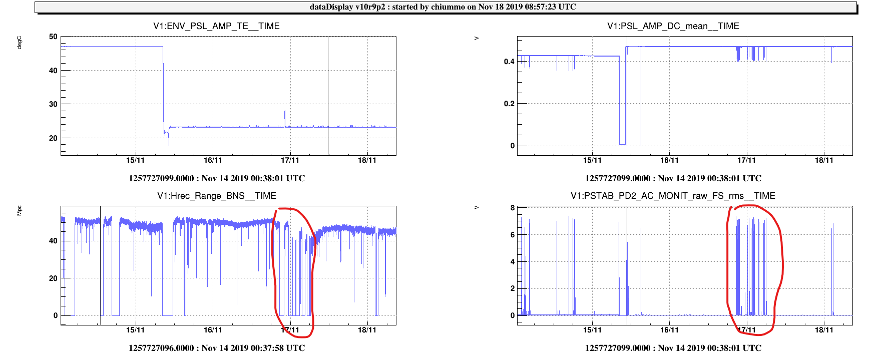
Then we installed a new chiller dedicated only to the neoan head in order to insure a better cooling down and validate the hypothesis that it will indeed bring the power up. It did (picture 2), with a temperature of about 23 degres instead of (more than) 47, we have about 0.47 V on the monitor at the output of the amplifier. We went back to the power that we had at the beginning of the run (picture 3).
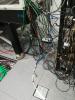
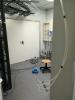
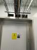
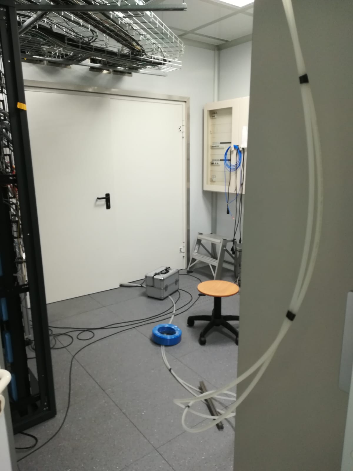
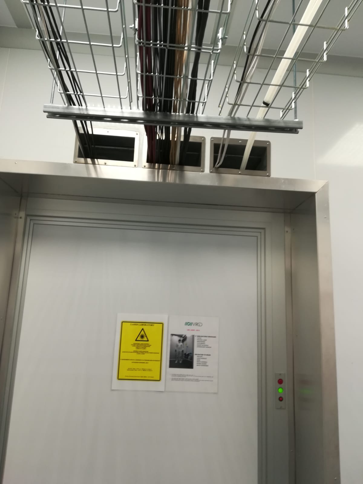
The chiller for now is installed in the electronic room next to the laser lab (the so-called "piscina"). It was, for the moment, the only way to keep it out of the laser lab. The pipes are passing through the dedicated passages above the doors. (pictures 4 5 6 and 7).
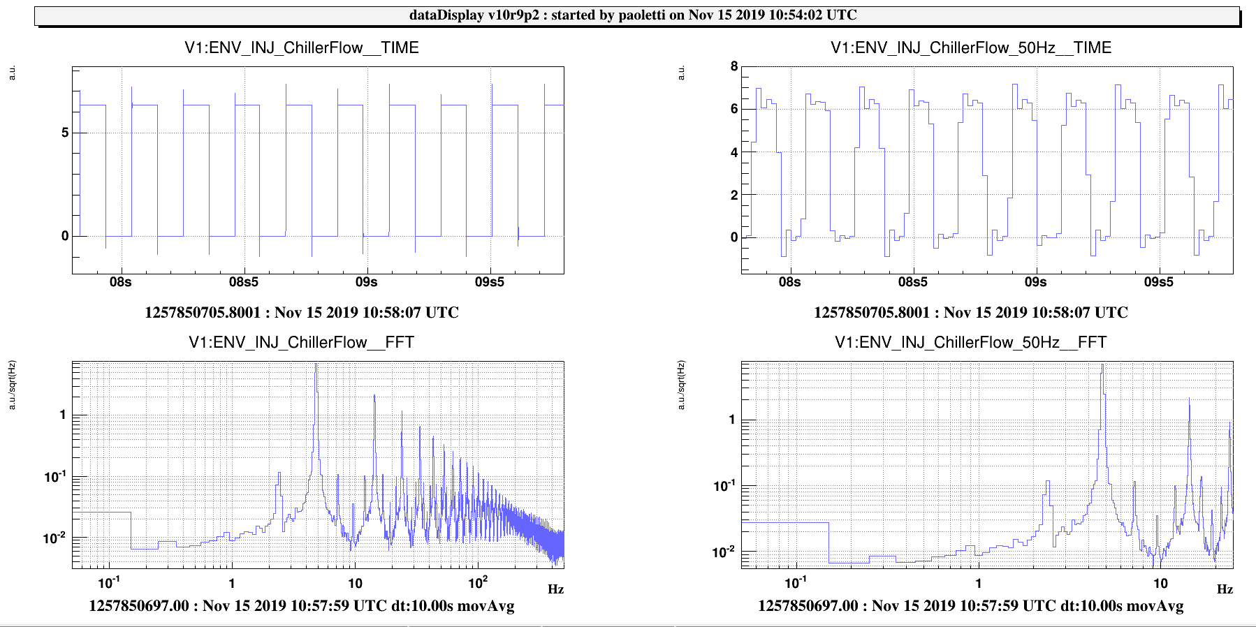
There is a new channel dedicated to the monitor of the flow of the chiller : ENV_INJ_ChillerFlow.
There is also a new flag on the DMS about the temperature of the neovan (22 < ENV_PSL_AMP_TE < 24)
Next steps will be to try if the previous chiller can do the job now that it seems that we remove the dirt from the tubing.
If not, we will keep this dedicated chiller till the end of the run but will arrange the path of the pipes.
