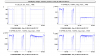
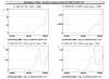
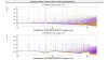
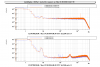
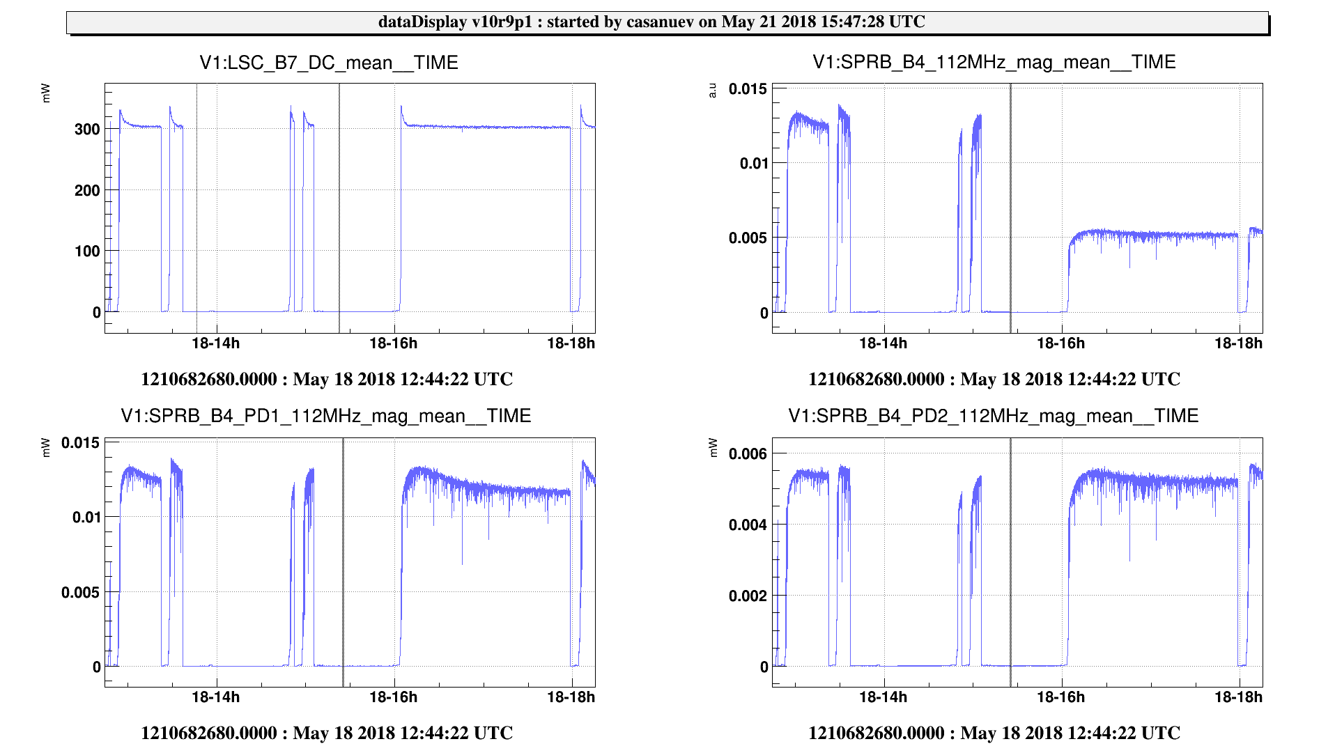
Last friday we looked a bit more in detail the content of the SPRB_112MHz_mag signal. There is a switch which changes between the equivalent signal coming from PD1 and coming from PD2. As we are actually using the error signal coming from PD2, friday around 16h UTC we switched to PD2. As it can be seen in Figure 1, at this moment, the sidebands decreased by a factor 2. This might be explained if PD2 is bigger than PD1 and so it cuts more the higher frequencies (to be confirmed by DET people). It seems consistant with the fact that the DC power is almost the same, and the 12 MHz also (see Figure 2).
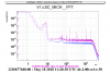
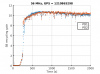
However, this signal SPRB_112MHz_mag is used to normalize the error signal of MICH in DF. We can see that the noise in MICH increases by a factor 4 when using the information coming from PD2 (see Figure 3). Notice that it might explain the increase of the coupling of MICH to DARM that we saw during the locks of the weekend. As soon as possible we will make some tests to try to understand the impact of the normalization on the sensitivity.
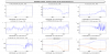
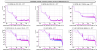
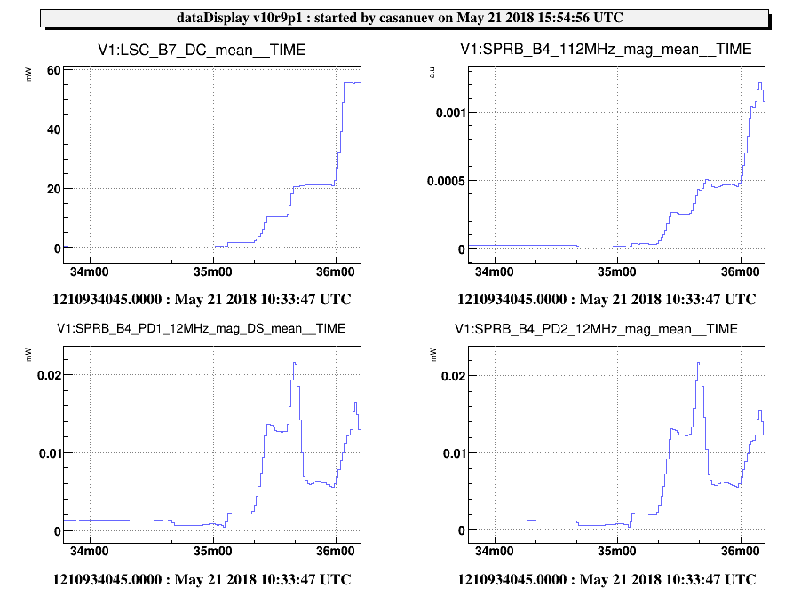
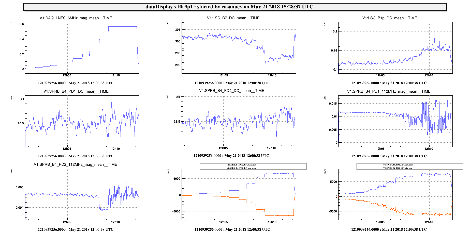
This morning I tried again to increase the 6MHz now that we have the 112MHz coming from both PDs. This time it did not unlock and we were able to increase the 6MHz up to 15 dBm (thsi is surely due to the fact that we are using now the good normalization). Figure 4 shows the behaviour of several signals while increasing the modulation depth. The B1p photodiode sees an increase of the power, due to the increase of sidebands that are recicled. Instead the arms see a decrease probably due to the loss of carrier towards the 6 MHz. Instead the B4 power remains constant combination of the increase of the recycling gain of the sidebands and the decrease of carrier power.
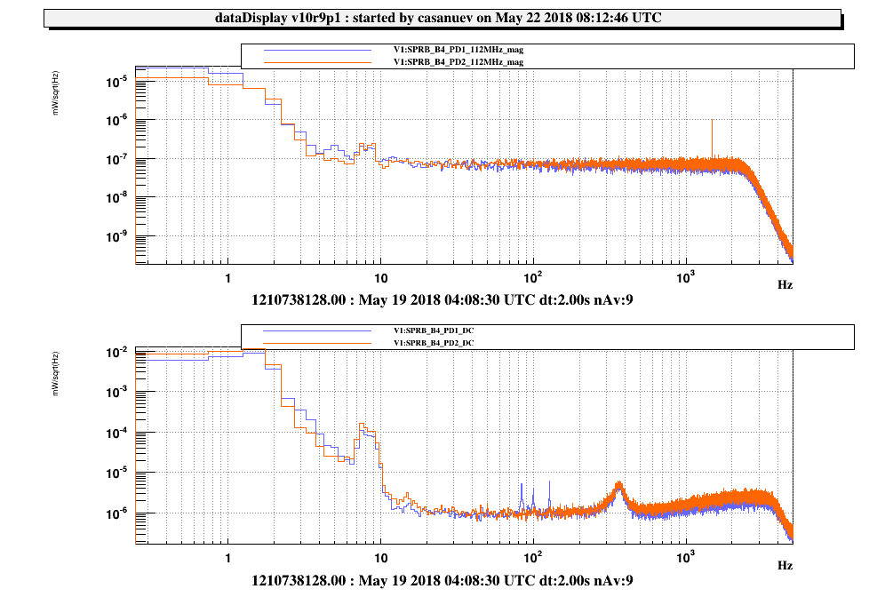
We can see that there is a decrease in the power of the 56 MHz of PD2 when reaching 12 dB and then it starts to oscillate at 15 dB. Notice that for PD1 this oscillation of the 112 MHz seems to occur already at 3 dB. To try to better understand this phenomena I made the spectrum of the DC of both PDs at 400MHz, which is shown in Figure 5. BLue is 15 dB of 6 MHz, violet is 12 dB, yellow is 9 dB and green is -15 dB. We can see a clear forest of lines for the 15 and 12 dB which can also be observed at 9 dB but much smaller. The 12 MHz seems to be the cause of this saturation.
With this information now can decide which is the "acceptable level" of modulation depth of the 6MHz so that we can study the 6MHz behaviour without causing problems of saturation also in PD2.