At around 08:30 UTC we went in TCS room where the power supply is located, and also looking at its analog display, we saw that it was delivering intermittently, as indicated by the LSC_WI_HB_moni signal.
We replaced the power supply with a spare one of the same kind (Kert 420). During the replacement (from 08:34 to 08:40 UTC) the operator temporarily opened the WI etalon loop, as recommended by Maddalena.
Now the loop seems working regularly (attached fig).

#10 (the pre-existing one)
#8 (the one installed on Tuesday 9th)
In order to debug the periodic glitches on PR horizontal accelerometers - that introduce a rotation of the F0 along ty and generate interferometer unlocks - a series of tests have been performed on Sa_PR control system during the last weeks:
- The sensing element of the accelerometers were re-centered.
- In order to identify possible communication problems on RapidIO bus, 'keep sample' has been enabled on coil driver DSP board code.
- In order to identify possible issues due to the distribution box, channels used by the in-air cables were swapped: horizontal accelerometers previously connected to channels 1,2,3 were moved to channels 4,5,6 and vertical accelerometers from #4,5 have been moved to #1,2.
- In order to identify possible issues due to the dedicated DSP boards, horizontal accelerometers have been connected to the DSP board previously connected to the vertical ones and viceversa. This operation has required a re-design of the controllers.
- In order to identify possible issues due to cabling, mechanical action on in-air cables was performed. Even though this test introduced similar glitches in the signals, they were longer respect to the ones causing the unlocks. Moreover similar actions on the accelerometer cabling of other towers produced similar results in ther respective signals.
Unfortunately all these were inconclusive. Even though the third test did not produce any change, we decided in any case to replace the distribution box this morning. Primary, secondary and feedback coils have been measured as well.
Waiting for new ideas about the origin of PR trips, a software mitigation of the problem has been implemented yesterday. The method is based on a few systematic characteristics of the trips:
1) the trip is anticipated by a fast glitch on the accelerometers;
2) the IP displacement along Z, which is the cause of unlock, is proportional to the IP rotation TY. This is a clean signal where one can read quite early the direction of the trip;
3) the trip can be well reproduced by adding a step to the accelerometers in a certain combination. The accordance is very good: very likely the trip is produced by a disturbance which adds a constant to the three signals. In principle, a mechanical disturbance (a tilt) can produce such an a effect on an accelerometer, but a common tilt on the structure where the three accelerometer are placed would produce basically a translation of IP. The large component of rotation seems definitely associated to an electrical disturbance on the sensors.
The fast glitch can be used as a trigger for producing an artificial step to be sent to the accelerometers. The TY signal can be used to know, in less than 1 second, the sign of the step needed to generate an opposite trip. In order to do that, the trigger is used to generate a time window (fig 1), during which TY is compared to a positive and a negative threshold. When a threshold is crossed, the appropriate step is sent. The step generates a trip only in Z combination, the only one which actually needs to be compensated. TY is not compensated, because interacting with the witness could produce a second dangerous crossing of the threshold.
This night two trips occurred: a large one (fig 2) and a small one (fig 3). Comparing the first to a similar past trip, one can see that the amplitude of the Z component has been reduced enough to avoid the unlock. Also the small one did not produce an unlock, but the figure shows that the compensation produced a dangerous trip in the opposite direction (over-compensation). The amplitude of the step has been defined in order to stay about in the middle between large and small trips, but we cannot exclude that a small harmless trip could be compensated so much to produce an unlock.
On this purpose, an improvement of the feed-forward can be studied, because the delay between the fast glitch and the TY crossing of a threshold contains the information to define a good amplitude of the step. Maybe it can be implemented after acquiring some statistics on the compensated trips.


A bug in the feed-forward code has been found and fixed. It was preventing the application of the step in some unlucky situation: that is the reason why the unlock has not been prevented during the latest PR trip.
Figure 1 and 2. I have looked at two example of the PR F0 accelerometer glitches in the raw_full data that are sampled at 10kHz. The glitch time scale is ~1ms.
The glitch is also visible in the COIL channels as pointed out by Didier this morning. But this seems rather like a consequences, as it happens a few ms later and has a longer time scale by a factor few. What are these COIL channels? Are these corrections of a feedback loop, and if yes what is its bandwidth?
The glitch is also visible in the V1 vertical accelerometer, but it has a different shape. It looks like a step. It is not present in the V2 vertical accelerometer. Is there something that is common between the H1, H2, H3 and V1 accelerometer, but different for the V2 accelerometer? For example is there a cable connector common to H1, H2, H3 and V1, but different for V2?
Figure 3 shows that the horizontal feedback of the accelerometer looks like a step response, so it might be that the horizontal accelerometer error signal doesn't look like a step, as the step is removed by the feedback loop, while for the vertical accelerometer it is not removed by the feedback loop keeping the proof mass centered inside the accelerometer.


This morning LVDT modulation frequency of the horizontal accelerometers has been changed (from 49.5 to 48.3 kHz). The demodulation phases has been adapted, the sensing elements have been re-centered, the TFs re-measured and the controllers re-estimated. Horizontal inertial damping gains has been re-measured as well and changed accordingly.
So far we had just one fast gitch on the three PR ACC, not too different from the usual ones, but it was not followed by any trip. Let's wait for the next.

After the modification of PR ACC H modulation frequency, we had 3 fast glitches - the usual rate observed recently - but no one triggered a trip. This is a good news: it seems that the problem has been fixed. To be noticed that the trips disappeared also from the vertical loop, but PR ACC V modulation frequency was not touched.

#10 (the pre-existing one)
#8 (the one installed on Tuesday 9th)
This is the list of the actions performed:
- thermal insulation of the room door (fig1)
- thermal insulation of the trapdoor (fig2)
- sealing of the passage holes for cables and pipes (figs 3-4-5)
- thermal insulation of the chiller pipe fittings (figs 6-7)
- moving the room temperature sensor to a position less subject to the fancoil air flow, and closer to the fancoil in-loop sensor (fig8). This is to have a better monitoring of the room temperature. The jump of about 1 degree in the temperature signal (fig9) is due to the new position of the sensor. No change in the set-point of the control loop.
Other actions may be done in the future, but to be agreed in advance with the TCS subsystem coordinator.


After yesterday intervention in TCS chiller room situation seems improved in terms of (~hours) oscillations induced by on/off around temperature threshold (see attached figure). Some thermalization seems still ongoing. TCS chillers temperatures look stable and uneffected by the change. TCS experts should check the impacts of the new woking point.

In Fig2 it is possible to see that the temperature of the TCS Chiller Room decreased down to around 22.5C after the refinement work by D.Soldani and R.Romboli on the additional air conditioning system installed to keep more stable the T in the room.


Yesterday afternoon, after the dailay meeting, we went in TCS room, to fix the problem of hight temperatures of WI TCS chiller reported by Ilaria N. To do that, we replaced the WI TCS chiller with the BCK; In place of this one, Marco and Nicola, mounted a chiller using the head of a spare one, and the body of the chiller used before as WI. During all these operations, both WI and NI CO2 lasers were kept ON and at the correct temperature. The spare chiller will be shipped to the firm to be repaired. Now the situation seems to be improved.

We were asked to do some measurements on NE mirror’s coils, as it is possible to do from the outer side.
We unplugged the STP Lemo cables from the “relay-box” and we measured some parameters of both WE (as reference) and NE coils.
Cables (AWG 24, resistivity 0.0892 ohm/meter) are approximately 9.5 meters long on the air side, and 28 meters long in the vacuum side, with many intermediate connectors, both in air and in vacuum.
We then estimate a [cabling + connectors] resistance of about 7 Ohm.
Using a DC resistance total mean value (as measured from the Lemo connectors) of 18.5 Ohm, we could say that the coils are 18.5 – 7 = 11.5 Ohm DC resistance.
We used a WAYNE KERR 6425 bridge for inductance measurement (data are not available for all eight coils, due to time constraint during the measurements):
| Coil name | R coil + R cable (DC) | L (mH) | Q | Self Res | eq. Self C | C to shield (nF) |
| WE DR | 18.55 | 14.570 | n.a. | 22.91 | 3.3123 | 8.46 |
| WE UR | 18.48 | n.a. | n.a. | n.a. | n.a. | 8.22 |
| WE DL | 18.62 | n.a. | n.a. | n.a. | n.a. | 8.44 |
| WE UL | 18.51 | n.a. | n.a. | n.a. | n.a. | 8.45 |
| NE DR | 18.56 | 14.398 | 4.045 | 22.91 | 3.3519 | 7.94 |
| NE UR | 18.40 | 14.369 | 4.065 | 22.91 | 3.3586 | 7.96 |
| NE DL | 18.53 | 14.388 | 4.035 | 22.91 | 3.3542 | 8.11 |
| NE UL | 18.48 | 14.411 | 4.058 | 16.66 | 6.3328 | 7.80 |
We also measured the DC resistance of all the coils wires relative to ground, which was always > 20 MOhm (full scale of the DMM).
At the end, we saved some plots (impedance Z, inductance L, quality factor Q) using an Agilent 4395A impedance analyzer (WE DR, and all NE coils) to cross-check the WAYNE KERR measurements. The 4395A interpolates the points (the frequency step around the self-resonance of the coils is about 1kHz), so the peak accuracy is rather low.
It is worth noting that:
- on the WE UL and NE UL coils has been physically "resting" a PT100-type temperature probe, with its own wiring that has nothing to do with the wiring of the coils themselves. This probe is held stationary in place with a few turns of insulated/enameled copper wire.
- the unusual value of the self-resonance frequency of the NE UL coil can be explained by an additional capacitance of about 3nF. This could be due to STP cabling being left connected on one side only (probably in the vacuum side), but not actually used (just a hypothesis, to be checked).


We now have some more information on the coils.
First of all, Fabio Gherardini told us that all UL coils in the cavity mirrors (certainly at the end mirrors, to be verified at the input mirrors) have a "split" wiring running from the coils to another flange, with the same length as the standard wiring.
This explains once and for all the mystery of the doubled capacitance reading on the NE_UL coil. One is supposed to find the same thing in all UL coils. The shield was taken out of the vacuum and left unconnected. It all fits, then.
We then had the opportunity to have a spare coil in our hands. So we measured it ourselves; the data are as follows:
- DC resistance 13.1 Ohm
- Inductance (@ 1 kHz) 14.489 mH
- Self-resonance around 190 kHz
- Calculated self-capacity ~ 48 pF
- Enamelled wire diameter 0.39 mm (assuming Grade 1 insulation, bare diameter should be 0.355 mm)
- Using a resistivity of 0.1727 Ohm/m, we have ~ 75 m of wire
The physical parameters are difficult to measure, we assume a throat width of 10 mm and a depth of 7 mm, so about 580 turns of wire.

Today we also measured the input towers. It is confirmed that they too have "spare" parallel wiring on one coil, per tower.
In detail:
- UL for the NI mirror
- DR for the WI mirror
We were asked to inject a sinusoidal sweep into the four NE MIR coils (one at a time) and check for any effects on the accelerometers in the vacuum chamber. The goal is to look for hidden defects in one or more of the coils: if they are "loose" they might vibrate, and the accelerometers might see this noise (the tower is still in-air).
We then injected the signal from 20 to 1000 Hz (600s for the first coil, 300s for the other three), amplitude 1V.
Looking by eye, we see no signal in the accelerometers.
Note: skilled researchers with fine ears were present in the tower during the test, who confirmed that no signal was heard.

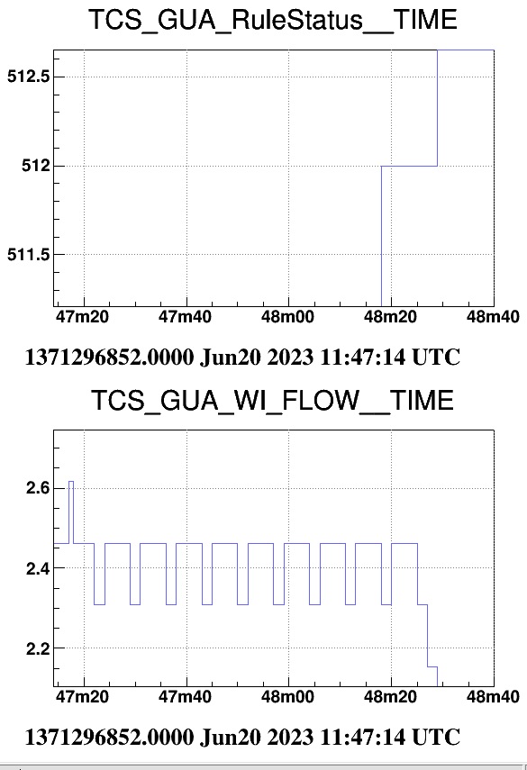
This morning at about 11h48 UTC the Tcs Guardian swapped the WI TCS chiller with BK TCS chiller. The cause has been the decrease of WI flow under the threshold of 2.6 L/min for a period of more than 60 secs. This threshold was appropriate when the flux was settled on ‘high’ state, but now in ‘medium’ state it is too strict. To fix this problem, we modified these thresholds:
Current thresholds of the flux {WI,NI} chiller:
1.6 L/min for more than 60 secs (before was 2.6 L/min)
1.3 L/min for more than 30 secs (before was 2.3 L/min)
1.1 L/min for more than1 sec (before was 2.1 L/min)


After equalizing the flux on all chillers setting the ‘medium’ state, the system works as expected.
To take in mind: in the previous settings, the WI and NI main chillers flux are settled on ‘high’ state, while the back up one was set to ‘medium’ .

Since June 5th at around 15 LT, the WI CO2 main laser temperature no longer settles on the chiller set point temperature (see fig.1).
To investigate the issue, we tried to change the chiller set point temperature by increasing it but the problem persisted (see fig.2):
-
June 6th: 13.57 UTC: 19.00 → 19.10 degree
- June 11th 19.36 UTC: 19.10 → 19.15 degree
One hypothesis to explain this anomalous behavior is a malfunctioning of the chiller, thus, this morning we performed a test swapping the WI chiller with the back up one.
The operation has been done at 8.55 LT (fig.3).
The test will go on all day.
Practial info:
1) yesterday the back up chiller temprature set point has been changed accordingly to the WI one (i.e 19.15 degree)
2) during the swapping of this morning, the pump speed of the back up chiller has been set from MEDIUM to HIGH and, at the same time, the pump speed of the WI chiller has been set from HIGH to MEDIUM.


The instability issue seems to be solved by replacing the WI chiller with the spare one (fig.1). To avoid possible risks in absence of the backup chiller, the old system has been restored at 16.30 UTC.
Tomorrow morning, the WI malfunctioning chiller will be replaced by the spare one.

Today checking the temperatures of three TCS chillers, I found that the WI TCS chiller temperatures no longer follows the set point temperature.
This unexpected behavior started on June 13th at about 14h30 UTC.
Another strange behavior is the sudden change of set point temperature (about every 20 minutes) of both Backup and WI TCS chiller.

After equalizing the flux on all chillers setting the ‘medium’ state, the system works as expected.
To take in mind: in the previous settings, the WI and NI main chillers flux are settled on ‘high’ state, while the back up one was set to ‘medium’ .
This morning at about 11h48 UTC the Tcs Guardian swapped the WI TCS chiller with BK TCS chiller. The cause has been the decrease of WI flow under the threshold of 2.6 L/min for a period of more than 60 secs. This threshold was appropriate when the flux was settled on ‘high’ state, but now in ‘medium’ state it is too strict. To fix this problem, we modified these thresholds:
Current thresholds of the flux {WI,NI} chiller:
1.6 L/min for more than 60 secs (before was 2.6 L/min)
1.3 L/min for more than 30 secs (before was 2.3 L/min)
1.1 L/min for more than1 sec (before was 2.1 L/min)
The CO2 powers have been checked and re-adjusted after the WI chiller false failure.
| CH [W] | INNER DAS [W] | OUTER DAS [W] | |||||
| nominal | measured | nominal | measured | nominal | measured | ||
| W | on the pickoff | 0.399 | 0.423 | 0.010 | 0.005 | 0.207 | 0.19 |
| N | on the pickoff | 0.535 | 0.547 | 0.052 | 0.052 | 0.535 | 0.535 |
Activity concluded at 16 UTC.
Consider that some thermal transients are still ongoing.
Today, at 15:33 UTC, during a rainstorm, a thunder struck around the southeast area of the Central Building, outside of the Gate (see map below). During this event, we saw a series of effects on the Interferometer, the most visible were the unlock of the Input Mode Cleaner and a jump in the timing of SSFS and LNFS (see plot #1).
A following event also triggered a missing data period (see plot #2).
The propagation time is visible in the Microphone, Accelerometer and Magnetometers roughly confirm the distance of the hit point. They are also visible in the Environmental Spectrogram (see plot #3).


After the Thunder Strike, the DAQ boxes located in Injection Electronic Lab and some of the SQZ system were in Timing error :
- Injection Electronic Lab: CEB_DBOX_LNFS, CEB_DBOX_SSFS and CEB_DBOX_ALS
- SQZ system: EQB1_DBOX_01, EQB1_DBOX_02, EQB2_DBOX_03, SQB2_DBOX_SBE and SQB2_DBOX_LC
They have been reconfigured yesterday
14:29 UTC, Wedn 17th - beginning of anomalous behavior on the ENEL (Fig1, Fig2)
14:33:45 UTC - malfunction of the CEB UPS --> accidental shutdown of CEB scientific equipment! (CEB=hall, DET area, INJ area, TCS room, SQZ). (Fig3) (note: CEB IPS remains ON at the begining of the CEB UPS blackout)
between 14:31 and 14:36 UTC - swaps at the UPSs input between ENEL and batteries for voltage anomalies (the channel denotes the UPS input: 1 = ENEL or generator, 0 = batteries)


The plant has a power of 20 KWp and we use it as a "pilot plant" in order to evaluate any disturbances that could propagate on our internal electricity grid, and in some way give problems to the experimental activities.
In the event that no noise or disturbance problems will result, then this energy self-production technology will be destined for future expansions according to the economic resources of EGO.
The plant is currently in the test phase and the daily production of energy is about 100 kWh, and it is expected that it will increase up to 150kWh/day in view of the good season.


At 10:35 UTC also the corresponding ACL servo loops were disabled.
We inspected the NEB air compressors room and identified the device responsible of this noise. It is the air dryer of the compressed air circuit. Figure 1 shows a picture of the device. Figure 2 shows the location of probe ENV_NEB_ AIR_COMP_LINE_PRES. Every 2 minutes or so this device produces an air puff in order to expell condensed water. This puff is associated to an audible acoustic noise. Red circles in Figure 3 indicate the measured times when the dryer puffed during our visit. These times match well with maxima of ENV_NEB_AIR_COMP_LINE_PRESS and noise transients in the NN_ACC sensor (inside NEB hall) and the NN_INF_07 microphone which is located in the water pumps room next to the compressors room.
The puffs of the dryer produce a little drop (~0.2 bar) of the pressure in the compressed air circuit, which seems to trigger (every even time) the start of the compressor.


At around 13:20 UTC, the cables connected to the unused coils (UL, DR) corresponding to DSP output channels DAC1 and DAC4 have been unplugged.
Yesterday in order to enable inertial damping control on both horizontal and vertical DOFs of the MC suspension, after the issue described in entry #59222, the accelerometer DSP boards have been replaced with an LVDT (serial #43129) and Coil Driver p4 (serial #42119) set. This intervention required the production and installation of a dedicated distribution box based on the design of the one installed at SR. Due to the DSP board configuration changes, for all the 5 accelerometers, the demodulation phases of the LVDTs and the transfer functions have to be re-measured. Moreover the LQG controllers have to be re-designed and implemented in the CD board. This latter task has been completed this morning.
The vertical and horizontal Inertial Damping (ID) loops are back in operation.
We went to the TEB pump room, and saw that the pumps were working, so we turned off the pumps and started looking for the loss in the circuit.
After some inspections in the CEB, we finally saw that the leak was in the cold exchanger of the DetLab AHU, located outside the CEB.
By acting on the appropriate valves, we have isolated this cold exchanger from the rest of the circuit, thus leaving the DetLab AHU functioning and fed only with hot water.
We then proceeded to restore all the lost water (several hundreds of litres), and then we restarted the circulation pumps and the chiller. In this way, around 12:00 the pressure and circulation of the circuit was restored. In the following 2 hours the thermal transient in TCS Chiller Room and DET EE Room ended, and the temperature returned to the normal value.
Next week the cold exchanger of the DetLab AHU will be repaired from an external firm, which for the moment is not critical, as we are in winter and the DetLab has not been affected by this failure.


.png)
This morning, at 09:42 UTC, with D. Soldani, we turned OFF the Air Handling Unit (CEB AHU) ventilation of CEB Clean Rooms for energy-saving reasons.
Concerning the CEB CleanRoom AHU "off condition" assessment.
A few observations concerning the behaviour of the clean area parameters and the achieved environmental noise reduction during the switch off.
The ClearRoom AHU has been kept off continuously for about 3 weeks, from December 16 to January 10.
Figure 1 shows the behaviour of the temperature and humidity of the Class 1 and Class 100 areas. Also the dust particle counters are shown but are not to be considered because likely unattendible. Figure 1 shows a long time stretch since the beginning of October.
At the end of October the temperature and humidity start fluctuating replicating the outside temperature (Figure 2). This is consequent to the closing of the warm and cold water flows into the HVAC heat exchangers but keeping the air fans running (energy saving test). In this configuration the inlet external air (which is substantial) temperature and humidity parameters are no more compensated by the heat exchanger control loops. The "problem" is the large external air flux, which although it has been set to the "minimum", looks still too large, as verified with inspection (Vincenzo and Davide). The replacement of the external air shutter with one with a more sutable range is planned.
When, between Dec. 16 and Jan 10, also the air fans have been turned off the temperature and humidity are more stable and the temperature stabilize at about 22 deg, that is +4deg respect to the HVAC full operation condition. This better stability is probably due to the fact that the external air inlet circulation reduces when the fans are stopped.
Figures 2,3,4 and 5 describe the reduction of noise in the CEB hall consequent to the switch off. Some vibration and acoustic lines disappear from the CEB floor (Figure 1) and vacuum chambers, in particular DT and IB (Figure 3). These lines have been identified, see https://tds.virgo-gw.eu/ql/?c=18442 or the LineDB. In particular disappear the infamous 18.5 and 16.4 Hz lines. Figures 4 and 5 are intensity maps of the NN-seismic-array (@Level 2) at the 18.5 Hz line, taken when the CleanRoom AHU is ON and then OFF, respectively. Note that there switching off the CR AHU causes no evident reduction of broadband noise, neither in seismometers or microphones (Figure 1, TOP plot). We know that the broadband acoustic and seismic noise in the CEB floor below ~10Hz is dominated by the HALL AHU. To complete the assessment of the CleanRoom AHU off condition the air contamination parameters need to be examined as well.


we started with an analysis of the behavior that occurred during the shift on Sunday 15th. All the relevant signals (described in https://logbook.virgo-gw.eu/virgo/?r=56251) are shown on the attached plot.
In the plot it can be seen that the voltages (V_IN, V_OUT) and current (I_OUT) are consistent with the command voltage (CHROCC_V_DAC channel). Instead the trend of the heater temperature (TE_IntHeater channel) is strange: when at a certain point the DAC control voltage is manually increased (from 0.38V to 0.42V), it happens that for the first few minutes the heater temperature decreases by about 7C instead of increasing immediately. Furthermore, after a few hours, when the control voltage has been restored to the initial value of 0.38V, the T of the heater does not return to the initial value (ie 156C), but remains a lower value (ie 148C). This raises suspicions more on the temperature sensing than on te heating system.
In the afternoon we started to do a test using another acquisition channel (at level of the IMMS box) for the TE_IntHeater sensor , and then at 17:14 UTC increased the Vdac to 0.42V for a short time, but the strange behavior happened again. Tomorrow we will proceed to replace the front-end electronics of the temperature sensor and check the behavior again.

This morning we tried to replicate the CHRoCC strange behavior observed yesterday. The command voltage sent with DAC (CHROCC_V_DAC channel) was incresed from 0.7V to 0.74V.
The initial heater temperature was 229°C (TE_IntHeater channel).
At the first trial (started at 9:18 UTC), the V_IN signal (the command voltage sent to KERT power supply), has been removed from DAQ ADCs and acquired with an external system.
The reflector temperature increases an decreases as expected without stange behaviors.
At the second trial (started at 10:03 UTC), when we connected also the DAQ ADC to acquire V_IN signal, again we didn't observe any strange behavior.
Setting V_DAC to the initial value (0.7V), the IntHeater temperature returns very close to the initial value.
A further test could be performed with V_DAC set to 0.38V.

Yesterday, we investigated again the CHRoCC strange behavior observed during the test of January, 15th, when an increase of Vdac, caused an initial negative transient of the IntHeater temperature.
During the new test, we were not able to reproduce the anomaly. The IntHeater temperature, increases and decreases with Vdac, as expected without opposite sign transients.

At 08:20 UTC, in agreement with Dattilo, Passaquieti and Soldani, I turned off the CEB AHU ventilation of the clean rooms, for energy saving (pict1).
To ensure the overpressure of the clean rooms of SIB2 I sealed, with tape, the communication door between SIB2 and the Clean Room (Pg). The door is now sealed and locked. In case of need, contact the Clean Op team.
The contamination levels of the CEB clean rooms are constantly monitored by a particle counter positioned in Class100 (plot attached).


.png)
Concerning the CEB CleanRoom AHU "off condition" assessment.
A few observations concerning the behaviour of the clean area parameters and the achieved environmental noise reduction during the switch off.
The ClearRoom AHU has been kept off continuously for about 3 weeks, from December 16 to January 10.
Figure 1 shows the behaviour of the temperature and humidity of the Class 1 and Class 100 areas. Also the dust particle counters are shown but are not to be considered because likely unattendible. Figure 1 shows a long time stretch since the beginning of October.
At the end of October the temperature and humidity start fluctuating replicating the outside temperature (Figure 2). This is consequent to the closing of the warm and cold water flows into the HVAC heat exchangers but keeping the air fans running (energy saving test). In this configuration the inlet external air (which is substantial) temperature and humidity parameters are no more compensated by the heat exchanger control loops. The "problem" is the large external air flux, which although it has been set to the "minimum", looks still too large, as verified with inspection (Vincenzo and Davide). The replacement of the external air shutter with one with a more sutable range is planned.
When, between Dec. 16 and Jan 10, also the air fans have been turned off the temperature and humidity are more stable and the temperature stabilize at about 22 deg, that is +4deg respect to the HVAC full operation condition. This better stability is probably due to the fact that the external air inlet circulation reduces when the fans are stopped.
Figures 2,3,4 and 5 describe the reduction of noise in the CEB hall consequent to the switch off. Some vibration and acoustic lines disappear from the CEB floor (Figure 1) and vacuum chambers, in particular DT and IB (Figure 3). These lines have been identified, see https://tds.virgo-gw.eu/ql/?c=18442 or the LineDB. In particular disappear the infamous 18.5 and 16.4 Hz lines. Figures 4 and 5 are intensity maps of the NN-seismic-array (@Level 2) at the 18.5 Hz line, taken when the CleanRoom AHU is ON and then OFF, respectively. Note that there switching off the CR AHU causes no evident reduction of broadband noise, neither in seismometers or microphones (Figure 1, TOP plot). We know that the broadband acoustic and seismic noise in the CEB floor below ~10Hz is dominated by the HALL AHU. To complete the assessment of the CleanRoom AHU off condition the air contamination parameters need to be examined as well.
This morning, at 09:42 UTC, with D. Soldani, we turned OFF the Air Handling Unit (CEB AHU) ventilation of CEB Clean Rooms for energy-saving reasons.